Fluorescence Compensation
All fluorochromes have excitation spectrum and emission spectrum. Within a flow cytometer, the appropriate ranges of emission wavelengths are selected by bandpass filters. However, when emission spectra overlap, fluorescence from more than one fluorochrome may be detected. In order to correct this spectral overlap, a process of fluorescence compensation is proposed. Compensation refers to the process of correcting the spillover from our primary signal in each secondary channel. This ensures that the fluorescence detected in a particular detector comes from the fluorochrome being measured.
By using fluorophores that do not have overlapping emission spectra, you can avoid the need for compensation. Alternatively, you can use fluorophores that can only be activated by specific laser lines, but as you increase the number of fluorophores, this becomes practically impossible.
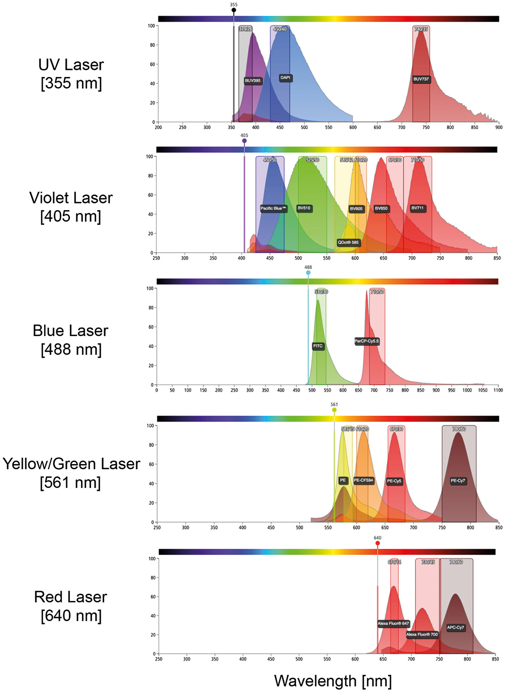 Figure 1. Schematic representation of diverse emission spectra.
In some experiments, FITC may be combined with other dyes, for example PE, which emit yellow and orange photons. In this case, the relative contribution of each fluorophore to the signal must be determined. The emission spectrum of FITC and PE are shown below (Figure 2). Also shown is a graphical representation of two typically used filters, 525/30 and 585/42, to detect these fluorophores. Marked by the arrow is the portion of the FITC spectrum that will be detected in the PE detector (585/42), which must be subtracted from the PE signal using compensation. This process becomes even more complicated when photons from multiple dyes are detected in each PMT.
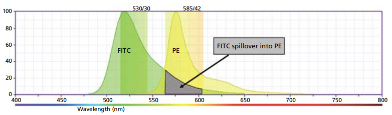 Figure 2. Example of FITC spillover into the PE channel.
When a sample is stained with both fluorophores, a double positive population will be observed without compensation. However, when using software to calibrate the compensation, the true level of staining is revealed. The software calculates the overflow values and applies it to the data to obtain correct compensation data. After compensating, we can see that there are actually no double positive cells, which is to be expected from these mutually exclusive markers.
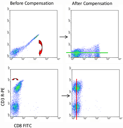 Figure 3. Fluorescence compensation corrects for spectral overlap.
Compensation Controls
Since compensation control is critical to determine the positive or negative of a given marker in an experiment, there are a few basic principles to keep in mind when designing compensation control for an experiment.
- In order to exclude the double-positive cells, the compensation control should be stained with a single color only.
- Negative and positive cells must have the same level of auto-fluorescence to avoid overcompensation.
- If an alternative marker is used to set compensation, it is crucial that the marker is at least as bright as the marker in the experimental sample.
- Compensation control samples must contain the same fluorochrome as the experimental samples.
References
- Roederer M. et al.; Spectral compensation for flow cytometry: visualization artefacts, limitations, and caveats. Cytometry, 2001, 45: 194-205.
- Tung J M. et al.; New approaches to fluorescence compensation and visualization of FASC data. Clinical Immunology, 2004, 110(3): 277-283.
Related Sections
Cell Services:
Cell Line Testing and Assays:
For research use only. Not for any other purpose.
Resources
- FAQ
- Posters & Downloads
- Protocol
- Cell Culture Guide
- Technical Bulletins
-
Explore & Learn
-
Cell Biology
- Monocytes vs. Macrophages
- How to Detect and Remove Endotoxins in Biologics?
- Comparison of Different Methods to Measure Cell Viability
- What Are Myeloid Cell Markers?
- How to Start Your Culture: Thawing Frozen Cells
- Biomarkers and Signaling Pathways in Tumor Stem Cells
- Techniques for Cell Separation
- Circulating Tumor Cells as Cancer Biomarkers in the Clinic
- CFU Assay for Hematopoietic Cell
- Comparison of the MSCs from Different Sources
- T Cell Activation and Expansion
- How to Isolate and Analyze Tumor-Infiltrating Leukocytes?
- Contamination of Cell Cultures & Treatment
- Generation and Applications of Neural Stem Cells
- Stem Cell Markers
- Cell Cryopreservation Techniques and Practices
- Guidelines for Cell Banking to Ensure the Safety of Biologics
- Critical Quality Attributes and Assays for Induced Pluripotent Stem Cells
- What Is Cell Proliferation and How to Analyze It?
- Direct vs. Indirect Cell-Based ELISA
- Comparison of Several Techniques for the Detection of Apoptotic Cells
- STR Profiling—The ID Card of Cell Line
- How to Assess the Migratory and Invasive Capacity of Cells?
- Cryopreservation of Cells Step by Step
- What are PBMCs?
- Quantification of Cytokines
- What Cell Lines Are Commonly Used in Biopharmaceutical Production?
- Neural Differentiation from Induced Pluripotent Stem Cells
- Isolation, Expansion, and Analysis of Natural Killer Cells
- Tumor Stem Cells: Identification, Isolation and Therapeutic Interventions
- Cell Culture Medium
- IL-12 Family Cytokines and Their Immune Functions
- Multi-Differentiation of Peripheral Blood Mononuclear Cells
- How to Scale Up Single-Cell Clones?
- What are Mesothelial Cells?
- T Cell, NK Cell Differentiation from Induced Pluripotent Stem Cells
- Major Problems Caused by the Use of Uncharacterized Cell Lines
- What are the Differences Between M1 and M2 Macrophages?
- Mesenchymal Stem Cells: A Comprehensive Exploration
- Human Primary Cells: Definition, Assay, Applications
- Enrichment, Isolation and Characterization of Circulating Tumor Cells (CTCs)
- Organoid Differentiation from Induced Pluripotent Stem Cells
- Tips For Cell Cryopreservation
- How to Decide Between 2D and 3D Cell Cultures?
- CHO Cell Line Development
- How to Eliminate Mycoplasma From Cell Cultures?
- Troubleshooting Cell Culture Contamination: A Comprehensive Guide
- Unveiling the Molecular Secrets of Adipogenesis in MSCs
- How to Isolate PBMCs from Whole Blood?
- How to Handle Mycoplasma in Cell Culture?
- Strategies for Enrichment of Circulating Tumor Cells (CTCs)
- ddPCR vs qPCR vs NGS: Which Platform Fits Your Research?
- Spheroid vs. Organoid: Choosing the Right 3D Model for Your Research
- From Collection to Cure: How ACT Works in Cancer Immunotherapy
- Role of Cell-Based Assays in Drug Discovery and Development
- Immunogenicity Testing: ELISA and MSD Assays
- What are White Blood Cells?
- Types of Cell Therapy for Cancer
- Optimization Strategies of Cell-Based Assays
- Live Cell Imaging: Unveiling the Dynamic World of Cellular Processes
- Overview of Cell Apoptosis Assays
- Cell-Based High-Throughput Screening Techniques
- Cell Immortalization Step by Step
- Adherent and Suspension Cell Culture
- From Blur to Clarity: Solving Resolution Limits in Live Cell Imaging
- Key Techniques in Primary, Immortalized and Stable Cell Line Development
- From Primary to Immortalized: Navigating Key Cell Lines in Biomedical Research
- Cell Viability, Proliferation and Cytotoxicity Assays
- What Are CAR T Cells?
- Eosinophils vs. Basophils vs. Neutrophils
- Cultivated Meat: What to Know?
- 3D-Cell Model in Cell-Based Assay
- What Are the Pros and Cons of Adoptive Cell Therapy?
- How to Maximize Efficiency in Cell-Based High-Throughput Screening?
- A Complete Guide to Immortalized Cancer Cell Lines in Cancer Research
- Exploring Cell Dynamics: Migration, Invasion, Adhesion, Angiogenesis, and EMT Assays
- Mastering Cell Culture and Cryopreservation: Key Strategies for Optimal Cell Viability and Stability
- Understanding Immunogenicity Assays: A Comprehensive Guide
-
Histology
- Fluorescent Nuclear Staining Dyes
- Stains Used in Histology
- Troubleshooting in Fluorescent Staining
- Immunohistochemistry Controls
- Overview of the FFPE Cell Pellet Product Lines
- How to Apply NGS Technologies to FFPE Tissues?
- Overview of Common Tracking Labels for MSCs
- Comparison of Membrane Stains vs. Cell Surface Stains
- Microscope Platforms
- Cell Lysates: Composition, Properties, and Preparation
- Multiple Animal Tissue Arrays
- Immunohistochemistry Troubleshooting
- Cell and Tissue Fixation
- Tips for Choosing the Right Protease Inhibitor
- Mitochondrial Staining
- Guides for Live Cell Imaging Dyes
- Instructions for Tumour Tissue Collection, Storage and Dissociation
- How to Choose the Right Antibody for Immunohistochemistry (IHC)
- How to Begin with Multiplex Immunohistochemistry (mIHC)
- Histological Staining Techniques: From Traditional Chemical Staining to Immunohistochemistry
- Common Immunohistochemistry Stains and Their Role in Cancer Diagnosis
- Modern Histological Techniques
- What You Must Know About Neuroscience IHC?
- How Immunohistochemistry Makes the Invisible Brain Visible?
- From Specimen to Slide: Core Methods in Histological Practice
- Multiplexing Immunohistochemistry
- Comparing IHC, ICC, and IF: Which One Fits Your Research?
- Serum vs. Plasma
-
Exosome
- How do PELN Deliver Drugs?
- Current Research Status of Milk Exosomes
- Collection of Exosome Samples and Precautions
- Classification, Isolation Techniques and Characterization of Exosomes
- Emerging Technologies and Methodologies for Exosome Research
- Common Techniques for Exosome Nucleic Acid Extraction
- How Important are Lipids in Exosome Composition and Biogenesis?
- Production of Exosomes: Human Cell Lines and Cultivation Modes
- What are the Functions of Exosomal Proteins?
- Exosome Size Measurement
- Exosomes as Emerging Biomarker Tools for Diseases
- How to Perform Targeted Modification of Exosomes?
- How to Apply Exosomes in Clinical?
- Techniques for Exosome Quantification
- How to characterize exosomes?
- Exosome Transfection for Altering Biomolecular Delivery
- Summary of Approaches for Loading Cargo into Exosomes
- Exosome Antibodies
- Exosome Quality Control: How to Do It?
- Applications of MSC-EVs in Immune Regulation and Regeneration
- The Role of Exosomes in Cancer
- How to Enhancement Exosome Production?
- What's the Potential of PELN in Disease Treatment?
- How to Efficiently Utilize MSC Exosomes for Disease Treatment?
- How to Label Exosomes?
- Unraveling Biogenesis and Composition of Exosomes
-
ISH/FISH
- ISH probe labeling method
- Multiple Approaches to Karyotyping
- In Situ Hybridization Probes
- CARD-FISH: Illuminating Microbial Diversity
- Comprehensive Comparison of IHC, CISH, and FISH Techniques
- RNAscope ISH Technology
- Multiple Options for Proving Monoclonality
- FISH Techniques for Biofilm Detection
- Whole Chromosome Painting Probes for FISH
- Overview of Common FISH Techniques
- Guidelines for the Design of FISH Probes
- Small RNA Detection by ISH Methods
- Differences Between DNA and RNA Probes
- Overview of Oligo-FISH Technology
- FISH Tips and Troubleshooting
- How to Use FISH in Hematologic Neoplasms?
- What are the Differences between FISH, aCGH, and NGS?
- Comparative Genomic Hybridization and Its Applications
- Telomere Length Measurement Methods
- Different Types of FISH Probes for Oncology Research
- What Types of Multicolor FISH Probe Sets Are Available?
- What Is the Use of FISH in Solid Tumors?
- Reagents Used in FISH Experiments
- What are Single, Dual, and Multiplex ISH?
- Mapping of Transgenes by FISH
- ImmunoFISH: Integrates FISH and IL for Dual Detection
- 9 ISH Tips You Can't Ignore
-
Toxicokinetics & Pharmacokinetics
- Organoids in Drug Discovery: Revolutionizing Therapeutic Research
- Toxicokinetics vs. Pharmacokinetics
- What Are Metabolism-Mediated Drug-Drug Interactions?
- How to Improve Drug Plasma Stability?
- How Is the Cytotoxicity of Drugs Determined?
- How to Improve the Pharmacokinetic Properties of Peptides?
- Traditional vs. Novel Drug Delivery Methods
- Key Factors Influencing Brain Distribution of Drugs
- The Rise of In Vitro Testing in Drug Development
- Overview of In Vitro Permeability Assays
- Predictive Modeling of Metabolic Drug Toxicity
- Effects of Cytochrome P450 Metabolism on Drug Interactions
- How to Improve Drug Distribution in the Brain
- Key Considerations in Toxicokinetic
- Organ-on-a-Chip Systems for Drug Screening
- What factors influence drug distribution?
- How to Design and Synthesize Antibody Drug Conjugates?
- What Is the Role of the Blood-Brain Barrier in Drug Delivery?
- Parameters of Pharmacokinetics: Absorption, Distribution, Metabolism, Excretion
- Physical and Chemical Properties of Drugs and Calculations
- Experimental Methods for Identifying Drug-Drug Interactions
- How to Conduct a Bioavailability Assessment?
- Comparison of MDCK-MDR1 and Caco-2 Cell-Based Permeability Assays
- Unraveling the Role of hERG Channels in Drug Safety
- Methods of Parallel Artificial Membrane Permeability Assays
- Pharmacokinetics Considerations for Antibody Drug Conjugates
- What Are Compartment Models in Pharmacokinetics?
- What are the Pharmacokinetic Properties of the Antisense Oligonucleotides?
- Pharmacokinetics of Therapeutic Peptides
- Comparing Plasma Protein Binding Methods
- Why iPSC-derived Cells are Useful in Toxicology?
- The Essentials of Quantitative Bioanalysis
- The 8 Costliest Mistakes in Preclinical CYP Phenotyping
- How Are Biomarkers Validated in Drug Development?
- Biomarkers vs. Functional Assays: Closing the Preclinical Gap
- When Should You Introduce ADME Tox Testing in Drug Development?
- How Can You Optimize Drug Toxicity Assessment?
- 6 Easy Steps to Get Your In Vitro ADME Done
- From Cells to Systems: Modern Approaches to Disease Modeling
- How to Choose the Right In Vitro ADME Assays for Small-Molecule Drugs
- What Are Biomarkers in Drug Discovery?
- The Bioanalysis Masterclass: Labile Metabolites
- How Genotoxicity Testing Guides Safer Drug Development
- Top 5 Pitfalls in In Vitro ADME Assays and How to Avoid Them
- 2D vs 3D Cell Culture Models: Which Is Best for Drug Toxicity Testing?
- Bioanalysis Errors: How to Spot and Fix Them Early
- Troubleshooting Common Issues in Drug Toxicity Testing
- What Is Genotoxicity in Pharmacology? Mechanisms and Sources
- Preclinical Workflow for Drug Toxicity Testing
- In Vitro ADME vs In Vivo ADME
- A Complete Guide to CYP Reaction Phenotyping in 2026
- Mastering the Noise: A Practical Guide to Minimizing Variability in Preclinical Studies
- How to Interpret CYP Phenotyping Data
- Reaction Phenotyping vs. Metabolic Stability
- The 8 Types of Drug Toxicity Every Researcher Must Know
- Why Cardiotoxicity Matters in R&D?
- What Are the Best Methods to Test Cardiotoxicity?
-
Disease Models
- Animal Models of Neurodegenerative Diseases
- Disease Models of Diabetes Mellitus
- Summary of Advantages and Limitations of Different Oncology Animal Models
- What Human Disease Models Are Available for Drug Development?
- Overview of Cardiovascular Disease Models in Drug Discovery
- Why Use PDX Models for Cancer Research?
- Preclinical Models of Acute Liver Failure
- Implementing NAMs in Drug Development
- Why Oncology Organoids Fail? How to Build Models That Work
- Organ-on-a-Chip: Is Your Microfluidic Setup Ready for Preclinical Trials?
- Oncology Model Strategy: From Screening to Validation
- How to Select the Right Preclinical Model for Drug Development
- How to Match Models to Drug Modalities: Small Molecules vs. Biologics
- How to Select the Right Humanized Mouse Model for Immuno-Oncology
- Animal Models vs. NAMs: Understanding Modern Preclinical Research
- Organoids vs Organ-on-Chip: Which is More Predictive?
- Humanized Mouse Models: Core Technical Considerations
- Static vs. Dynamic In Vitro Models
-
Cell Biology
- Life Science Articles
- Download Center
- Trending Newsletter